Design physical products with AI: hands-on with text-to-cad
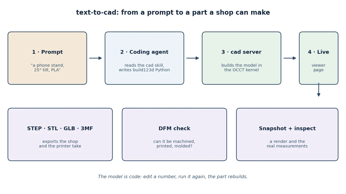
text-to-cad (earthtojake/text-to-cad, 26,000+ GitHub stars, MIT) turns your coding agent into a CAD engineer: it writes build123d Python, a local server builds it, and the same pipeline checks whether a shop can actually make the part. This tutorial installs it, connects an agent, and builds a parametric phone stand from prompt to printable STL.
- Model as code: parts are build123d Python scripts — edit a number, run it again, and the part rebuilds.
- Deterministic kernel: a local server builds the geometry with OpenCASCADE; the first build loads the kernel (about 240 MB, once), warm rebuilds take under a second.
- Manufacturing checks built in: CNC, sheet metal, injection molding, and 3D printing, with the exact failing edge and limit named.
- Verified here: a bracket at 40 × 20 × 6 mm, and a phone stand at 100 × 108.1 × 92.1 mm and 100,603 mm³ — its STEP file reads back with identical measurements, and its print check passed with one real warning.
- Cost: text-to-cad is free and MIT licensed; the model behind your coding agent is the only paid part.
Most AI coding tools stop at text. text-to-cad doesn't: it turns your coding agent into a CAD engineer. You describe a part in plain English, the agent writes it as Python, and a local server builds the real geometry — then checks whether a machine shop or a 3D printer can actually make it. The project (earthtojake/text-to-cad) has 26,354 stars on GitHub, with about 7,000 of them added in the month to November 12, and it is the most complete version of this idea yet: not a demo, but a working pipeline from prompt to STEP file.
This tutorial installs text-to-cad, connects it to a coding agent, and builds a parametric phone stand from scratch — then exports it as STEP and STL, runs the manufacturing check, and renders it. Every command below ran in a sandbox; the outputs quoted are the real ones.
Why text-to-cad is spiking now#
The idea of "AI writes CAD" is not new. What changed is the shape of the answer. Early tools asked a model to emit a mesh or a blob of geometry and hoped for the best. text-to-cad makes the model write a program — a build123d Python script — and then runs that program through a real CAD kernel (OpenCASCADE) on your own machine. The model is code, so it is parametric, editable, and reviewable. Change a number, run it again, and the part rebuilds. That is the difference between a picture of a part and a part.
Three things make it worth your time over the alternatives:
- The server, not the model, owns the geometry. A warm local server (port 3245 by default) builds the model, caches it, and replays only what an edit touched. A comment-only edit re-runs nothing; a dimension edit re-runs what reads it. In the sandbox, a first build took 32 seconds (mostly loading the kernel the first time) and a warm rebuild of a second variant took 0.49 seconds.
- It checks whether the part can be made. The same pipeline runs design-for-manufacture checks: CNC milling, sheet metal, injection molding, or 3D printing. It reports real numbers — wall thickness, overhangs, support volume — and names the exact edge that fails. My phone stand passed its print check with one genuine warning, which the tool explained and I could act on.
- It is a whole workshop, not one skill. The install ships eight skills: CAD modeling, engineering drawings, finite-element stress checks, KiCad circuit boards, 3D-print slicing, renders, robot simulation (URDF/SRDF/MJCF), and a SendCutSend fabrication check. One install covers the path from a prompt to a part, a drawing, and a quote.
The numbers behind the spike: 26,354 stars, 2,512 forks, 1,511 commits, and 108 releases since the project was created on April 22, 2026 — MIT licensed, with releases landing frequently enough that the installer I ran pulled 0.11.10 the same week it shipped.
What you'll need#
- A computer running Linux, macOS, or Windows. No GPU is needed — the CAD kernel runs on CPU. The first build downloads a kernel environment of about 240 MB (about 620 MB on disk), so budget roughly 1 GB free.
- A coding agent. Claude Code, Codex, Cursor, Grok Build, or Gemini CLI — the installer wires the plugin into whichever it finds. The agent is where the model lives, so its cost is whatever your agent subscription or API key costs. text-to-cad itself is free and MIT licensed.
- About 15 minutes. The install takes a couple of minutes; the first build takes another minute while the kernel environment is created.
- Nothing else to buy. The
uvpackage manager is installed for you if it is missing, and the Python the server runs on (3.14) is managed byuv— it never touches your system Python.
Two defaults to know before you start: the installer turns usage telemetry on (anonymous stats and crash reports, tagged with a random ID), and automatic updates on. Both can be switched off — cad telemetry off and cad update auto off — and the install command takes a --no-telemetry flag, which is what I used in the sandbox.
Step 1 — Install it#
Download the installer first so you can read it before it runs, then do a dry run to see the plan:
curl -fsSL https://texttocad.dev/install.sh -o install.sh
sh install.sh --dry-run
The dry run prints what it will do for every agent app it finds — install, leave alone, or skip — and changes nothing. On a machine with no agent apps installed it simply reports that, and still sets up the cad command. Then run it for real:
sh install.sh --no-telemetryWhat it does: finds or installs uv, then runs cad setup from the latest release (0.11.10 in this run) through uvx, which downloads Python 3.14.10 (35.1 MB) and the cad-server package. It writes the cad command to ~/.local/bin/cad, writes the plugin folder, and points each agent app it finds at that folder. It installs no CAD kernel yet — that is created on first need, when you build your first model. The install ends by listing which apps to restart. In the sandbox the whole thing finished in under a minute and reported:
server   registered 0.11.10 (~/.local/state/cad/installations/0.11.10.json)
command  ~/.local/bin/cad written
telemetry off: your choice
Verify the install with the doctor command, which reports and changes nothing:
export PATH="$HOME/.local/bin:$PATH"
cad doctor --check
You should see the release, the Python, and the plugin path, plus a line saying the kernel is "not made — made on first need". If cad is not found, your shell has not picked up ~/.local/bin yet — either export the PATH as above or open a new terminal.
Step 2 — Connect your coding agent#
The installer does the wiring for the apps it finds. On the sandbox machine it installed the plugin into Codex and copied the skills into the shared skills folders for OpenCode, OpenClaw, and Antigravity CLI. I confirmed the Codex registration directly:
$ codex plugin list
Marketplace `text-to-cad`
PLUGIN                   STATUS              VERSION  SOURCE
text-to-cad@text-to-cad  installed, enabled  0.11.10  /home/hatch/.local/state/cad/plugin
For Claude Code, the project's install guide gives two commands (documented there; this sandbox has no Claude Code to run them against):
claude plugin marketplace add earthtojake/text-to-cad#latest
claude plugin install text-to-cad@earthtojake
What each app gets is the same plugin: the skills plus the CAD server configuration. Claude Code gets the skills (its Code tab reads the server from Claude Desktop's config); Codex gets a copy of the plugin; Cursor, Grok Build, and Gemini CLI get it through their own plugin mechanisms; agents without a plugin get the skills alone, copied in by the Skills CLI. Restart the app after installing so it loads the new plugin. You can check what landed where at any time with cad doctor — it lists each app and the version it holds.
Once the plugin is in, the agent has eight skills to call on: cad for modeling, engineering-drawing for dimensioned PDF sheets, fea for stress checks, pcb for KiCad boards, print3d for slicing, render for stills and turntables, robot-simulation for URDF/SRDF/MJCF descriptions, and sendcutsend for fabrication checks. The agent picks the skill from your request; you never invoke one by hand.
Step 3 — Build your first part#
Before asking an agent to design anything, build a part yourself so you know what a good result looks like. A model is a Python function decorated with @model that returns a build123d shape. This is the example from the project's own cad skill — a bracket with a hole — run verbatim:
import build123d as bd
from cad import model


def bracket_body(width, thickness, bore):
    body = bd.Box(width, 20, thickness)
    hole = bd.Cylinder(bore / 2, thickness)
    body = body - hole
    body.label = "bracket"
    body.color = "#4a6fa5"
    return body


@model
def bracket():
    return bracket_body(40, 6, 8)


@model
def bracket_wide():
    return bracket_body(60, 6, 8)


if __name__ == "__main__":
    bracket()
    bracket_wide()
Run it with cad run, which works like uv run — same options, same script header, nothing to set up:
cad run src/bracket.pybuilt src/bracket.py::bracket cold in 32.26s: bodies 1 run; 6 misses, 0 hits; body 0.40s, names 0.42s, document 0.02s
parts 1 · bounds 40 × 20 × 6 mm · joints 0 · sequences 0
id: 4bbea437-b42c-5770-8997-c8b2795ab42e
view: http://127.0.0.1:3245/4bbea437-b42c-5770-8997-c8b2795ab42e?token=...
built src/bracket.py::bracket_wide warm in 0.49s: bodies 1 run; 6 misses, 0 hits; body 0.04s, names 0.00s, document 0.00s
parts 1 · bounds 60 × 20 × 6 mm · joints 0 · sequences 0
id: bc7e1679-c0b6-54cf-aa0a-578608277c6cRead that output carefully, because it is the whole system in miniature. The first build took 32 seconds — that is the kernel environment being created and loaded for the first time, not the part (the part itself built in 0.40 seconds). The second variant built warm in 0.49 seconds. Each model gets a stable id derived from its script path and function name, so it is the same run after run, and a view: link that opens the model in the local viewer. The bounds line — 40 × 20 × 6 mm — is your first check: it should match the numbers you wrote. If it doesn't, the model is wrong, and you find out now instead of at the printer.
Two rules from the skill that save real debugging time: keep the model calls under if __name__ == "__main__": so other scripts can import the models, and never read a number off a picture — a render shows arrangement, not dimensions. Use cad model inspect for numbers.
Step 4 — End to end: a parametric phone stand#
Now the real test: a part designed for a process. The request is a phone stand for 3D printing in PLA — a flat base, a backrest leaning 25 degrees from vertical, a front lip that stops the phone sliding forward, and a cable slot through the bottom of the backrest so a charging cable passes behind the phone. In the normal flow you would hand that paragraph to your agent and it would write the script. Here is the script, exactly as it ran in the sandbox, so you can see what the agent is supposed to produce — every dimension a named constant at the top, one @model function, millimetres throughout, +Z up:
"""A parametric phone stand, 3D printed in PLA.

Design: a flat base, a backrest leaning 25 degrees from vertical, and a
front lip that stops the phone sliding forward. A cable slot through the
bottom of the backrest lets a charging cable pass behind the phone.

Check: cad model dfm "$ID" --process printing --technology fdm --material pla
"""

from __future__ import annotations

import math

import build123d as bd
from cad import model

# --- Parameters (millimetres, degrees) -------------------------------------
PHONE_WIDTH = 78.0
PHONE_THICKNESS = 9.0
BASE_LENGTH = 100.0  # x, across the phone
BASE_DEPTH = 70.0  # y, front to back
BASE_THICKNESS = 6.0
BACK_HEIGHT = 95.0  # along the lean
BACK_THICKNESS = 6.0
BACK_TILT_DEG = 25.0  # from vertical, leaning back
LIP_HEIGHT = 12.0
LIP_THICKNESS = 6.0
CABLE_SLOT_RADIUS = 4.0


def _backrest_profile() -> bd.Solid:
    """The backrest as an extruded YZ profile: a parallelogram leaning back."""
    tilt = math.radians(BACK_TILT_DEG)
    rear_y = -BASE_DEPTH / 2.0 + 2.0  # back edge sits 2 mm in from the base rear
    front_y = rear_y + BACK_THICKNESS
    top_shift = BACK_HEIGHT * math.sin(tilt)
    top_z = BASE_THICKNESS + BACK_HEIGHT * math.cos(tilt)
    with bd.BuildPart() as back:
        with bd.BuildSketch(bd.Plane.YZ):
            bd.Polygon(
                [
                    (rear_y, BASE_THICKNESS),
                    (front_y, BASE_THICKNESS),
                    (front_y - top_shift, top_z),
                    (rear_y - top_shift, top_z),
                ],
                align=None,
            )
        bd.extrude(amount=BASE_LENGTH)
    part = back.part.moved(bd.Location((-BASE_LENGTH / 2.0, 0.0, 0.0)))
    part.label = "backrest"
    return part


@model
def phone_stand():
    """Return the phone stand model in millimetres."""
    with bd.BuildPart() as stand:
        # Base plate.
        bd.Box(
            BASE_LENGTH,
            BASE_DEPTH,
            BASE_THICKNESS,
            align=(bd.Align.CENTER, bd.Align.CENTER, bd.Align.MIN),
        )
        # Backrest, leaning back.
        bd.add(_backrest_profile(), mode=bd.Mode.ADD)
        # Front lip: stops the phone sliding off the base.
        lip_y = -BASE_DEPTH / 2.0 + BACK_THICKNESS + PHONE_THICKNESS + LIP_THICKNESS / 2.0
        with bd.Locations(bd.Location((0.0, lip_y, BASE_THICKNESS))):
            bd.Box(
                BASE_LENGTH,
                LIP_THICKNESS,
                LIP_HEIGHT,
                align=(bd.Align.CENTER, bd.Align.CENTER, bd.Align.MIN),
                mode=bd.Mode.ADD,
            )
        # Cable slot through the bottom of the backrest.
        slot_y = -BASE_DEPTH / 2.0 + 2.0 + BACK_THICKNESS / 2.0
        with bd.Locations(bd.Location((0.0, slot_y, BASE_THICKNESS + 6.0))):
            bd.Cylinder(
                radius=CABLE_SLOT_RADIUS,
                height=BACK_THICKNESS + 4.0,
                rotation=(90.0, 0.0, 0.0),
                align=(bd.Align.CENTER, bd.Align.CENTER, bd.Align.CENTER),
                mode=bd.Mode.SUBTRACT,
            )

    part = stand.part
    part.label = "phone_stand"
    return part


if __name__ == "__main__":
    phone_stand()
Run it:
cad run src/phone_stand.pybuilt src/phone_stand.py::phone_stand cold in 4.43s: bodies 1 run; 32 misses, 0 hits; body 1.00s, names 0.07s, document 0.00s
parts 1 · bounds 100 × 108.1 × 92.1 mm · joints 0 · sequences 0
id: b7e6fd15-253e-5e53-bdc8-15b02db54e1c
view: http://127.0.0.1:3245/b7e6fd15-253e-5e53-bdc8-15b02db54e1c?token=...Check the bounds against the design before you believe anything else. The base is 100 mm wide, so the X bound is 100. The height should be the 6 mm base plus the backrest's vertical rise, 95 × cos(25°) ≈ 86.1 mm — 92.1 mm total, exactly what the build reports. The depth is 108.1 mm: the 70 mm base plus the backrest's backward lean, 95 × sin(25°) ≈ 40.1 mm, minus the 2 mm inset — 70 + 40.1 − 2 = 108.1. Every number in the output is derivable from a constant in the script, which is the point: a parametric model is checkable arithmetic, not a black box. Save the id — every command after this one takes it.
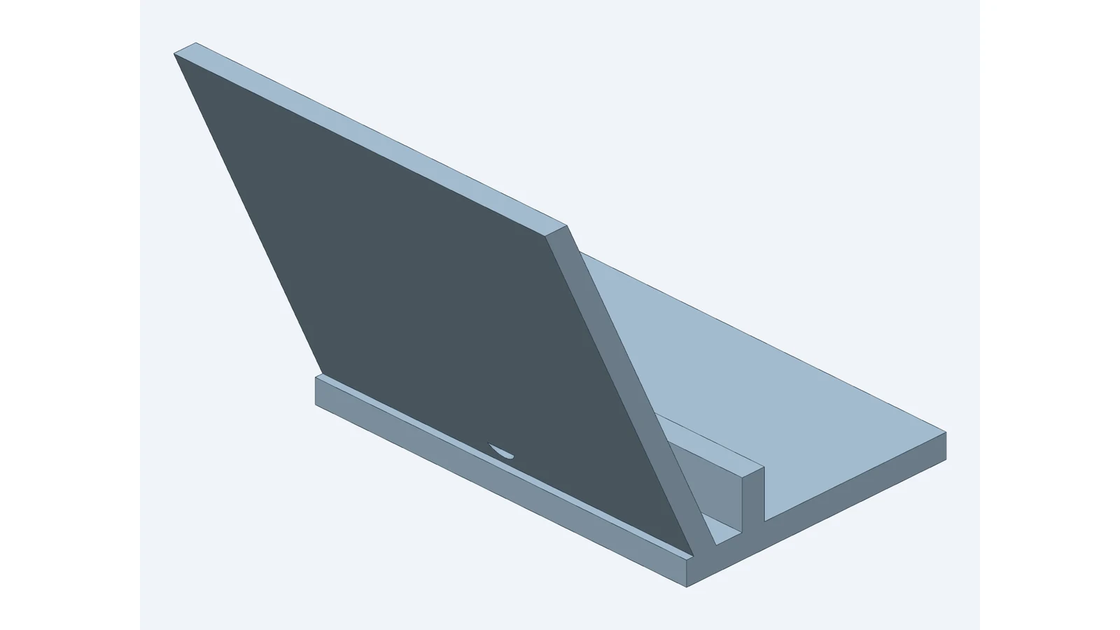
Now ask the agent for the same part in words, and compare. A good prompt names the process, the material, and the numbers: "Design a phone stand for FDM printing in PLA. Base 100 × 70 × 6 mm. Backrest 95 mm tall, 6 mm thick, leaning 25 degrees from vertical. A 12 mm lip at the front, and an 8 mm cable slot through the bottom of the backrest. Export STEP and STL, run the print check, and show me a snapshot." The agent writes the script, runs it, and hands you the id. If its numbers disagree with the bounds line, send it back — the bounds line is the referee.
Step 5 — Export files a shop and a printer can use#
A file is an action on the document the server holds — never part of the model, and written only when asked. Export the STEP for CAD interchange and the STL for the printer:
ID=b7e6fd15-253e-5e53-bdc8-15b02db54e1c
cad model export "$ID" out/phone-stand.step
cad model export "$ID" out/phone-stand.stl --tolerance 0.02
wrote out/phone-stand.step (56.6 KB) in 0.10s
wrote out/phone-stand.stl (11.9 KB) in 0.09sTwo details matter. First, the STEP and the STL go in separate commands: the --tolerance option meshes STL, GLB, and 3MF files finer, and an export that takes it may name only mesh files — a STEP among them refuses the whole export, and nothing is written. Second, every export is checked before anything is written: a refused export writes no files at all, so you never get a half-written STEP.
Verify the export round-trips — read the file back through the same kernel and compare:
cad step inspect out/phone-stand.stepphone_stand 49d6c907-3f01-5123-b6cf-5a5b58ddf721
state file /home/hatch/workspace/oss-desk-sandbox/phone-stand/out/phone-stand.step
parts 1 in phone_stand
bounds 100 x 108.1 x 92.1 mm, from (-50, -73.15, 0)
volume 100,603 mm^3Same bounds, same volume (100,603 mm³) as the live document — the file carries the part faithfully. The STL is a binary mesh of 242 triangles. GLB and 3MF export the same way, and a 2D profile exports as DXF. For a project with standing deliverables, the skill recommends an exports.py that imports the models and rewrites every file on each run.
Step 6 — Check it can actually be printed#
This is the step other AI-CAD tools skip, and the reason to use text-to-cad for anything you intend to make. Run the manufacturing check for the process you named:
cad model dfm "$ID" --process printing --technology fdm --material plawarning: printing.knife_edge at phone_stand/phone_stand/edge 26: material at a knife edge
(a convex edge under 45 deg) 0 mm is under the 0.8 mm recommended minimum
(the tip prints rounded) Hint: blunt it -- a flat or round at least 0.8 mm across --
or open its angle to 45 deg or more. Source: text-to-cad, its own figure: no published
guide states one.
OK b7e6fd15-253e-5e53-bdc8-15b02db54e1c: 1 warning(s); printing fdm: 100603 mm3,
1 body(ies); overhangs under 45 deg 0 mm2; walls min 1.228, p05 5.4378, median 6 mm;
support ~152.93 mm3The verdict is OK with one warning — and the warning is real. The top edge of the leaning backrest comes to a sharp point where the parallelogram's top face meets its face; a 3D printer cannot resolve a zero-width edge, so the tip prints rounded. The check names the exact edge (edge 26), the rule, the limit (0.8 mm), and the fix (blunt it with a flat or round at least 0.8 mm across, or open the angle). That is a check earning its keep: it caught a defect in a design I wrote, and told me precisely how to fix it.
The rest of the line is the printability summary: 100,603 mm³ of material, no overhangs under 45 degrees, thinnest wall 1.228 mm, about 153 mm³ of support. The same command checks CNC milling (--process cnc --material aluminum --tools 3,6,10), sheet metal, and injection molding. Two exit-code rules to remember: exit 0 is OK, exit 1 is FAILED (a finding is an error), and exit 3 is NOT CHECKED — which is never a pass. If a check reports NOT CHECKED, fix what it names or run it again; never hand a part off on it. And the checks are general practice, not any shop's limits — for a named shop, compare the measurements against its published limits.
If you declare the process in the model itself — for example part.material = metals.aluminum(process=machined()) — then cad model dfm "$ID" with no flags checks it for what it says it is. The project's guidance is to design for the process from the first line, record it in the model, and run the same check after every edit.
Step 7 — Look at it: snapshots and the viewer#
The view: link from the build opens the model in the local viewer — a page served from your own machine on port 3245, with a per-document token in the URL. But never screenshot the viewer to check your own work. The right tool is a snapshot, drawn by the same OCCT renderer the viewer uses, straight to a PNG:
cad model snapshot "$ID" out/phone-stand.pngwrote out/phone-stand.png (1600x1200, solid) in 6.66sThe render at the top of Step 4 is that file. Snapshots take options for camera (--camera top), display mode (solid, hidden-line, wireframe, xray), and poses for mechanisms — for an assembly, look at each part alone before it is placed, then at joints at both ends of their travel, and only then at the whole. A snapshot shows arrangement and appearance, never dimensions: if you need a number, cad model inspect "$ID" gives it. On this run it reported the bounds, the volume (100,603 mm³), and the exact library versions behind the build: build123d 0.13.0, OCP 8.0.1.1.0, Python 3.14.10.
Useful housekeeping commands while you work: cad status lists the server's workers and the documents it holds (on this run: three live documents, workers 3/4, about 1.9 GB RSS), and cad stop stops the server. A build cut off by a shell timeout keeps running in the server — run the same command again and it waits for that build and replays it. And cad update moves the machine to the newest release when one ships.
When to use this vs the alternatives#
| Tool | Best for | Watch out for |
|---|---|---|
| text-to-cad | Parts you intend to make: parametric models in Python, manufacturing checks, drawings, FEA, PCBs | Needs a coding agent with a model; first build downloads a ~240 MB kernel |
| SolidCraft | Parametric CAD driven over MCP with JSON model definitions and a command registry | A different authoring model — JSON, not Python scripts |
| sand3d | Quick Python 3D models your LLM can generate, light and fast | No manufacturing checks or viewer; a lighter tool for a lighter job |
| mcp-for-blender | Driving Blender scenes and renders from an LLM | Scenes and meshes, not engineering parts with tolerances |
| FreeCAD (GUI) | Hands-on modeling when you want to draw, not prompt | No agent, no skills, no checks — you are the operator |
The dividing line is the deliverable. If the end of the job is a picture or a scene, use a Blender route. If it is a script you will keep editing, sand3d is lighter. If it is a part with tolerances, a material, and a process — something a shop or a printer has to accept — text-to-cad is the one that checks its own work. That check is the feature: everything else in this space will happily hand you a beautiful, unmakable part.
Honest limitations#
- The agent step needs a model you pay for. text-to-cad is free, but the coding agent that writes your models runs on a subscription or an API key. Everything deterministic — install, build, export, checks, snapshots — was verified in the sandbox with no key at all. The Claude Code plugin commands are quoted from the project's install guide, not run here; the Codex path was verified instead.
- The first build is the slow one. The kernel environment downloads once (~240 MB) and the first build loads it; after that, warm rebuilds take under a second. The engine is also heavy at rest — about 1.9 GB RSS with three workers on this run.
- The agent can still write a bad model. A plausible-looking script with wrong dimensions builds without complaint. The defense is the bounds line on every run, plus
inspectand snapshots. Never skip the bounds check. - Defaults to review: telemetry and automatic updates are both on unless you switch them off, and the installer touches every agent app it finds — run
--dry-runfirst if you want to see the plan. - Checks are general practice. The DFM rules come from published design guides and the project's own figures where no guide states a limit. They are not your shop's limits; confirm critical tolerances with the shop.
The takeaway#
text-to-cad earns its spike by closing the loop other AI-CAD tools leave open. The model is code you can read and change. The build is deterministic and fast once warm. The export is a real STEP file that reads back with identical measurements. And the manufacturing check catches real defects — a knife edge in a design I wrote — before the part reaches a printer. Install it with one command, connect the agent you already use, and start with a part you can measure: if the bounds line matches your numbers, the pipeline works, and everything after that is just more ambitious parts.
Sources#
- earthtojake/text-to-cad on GitHub — repository, README, and skills (cad skill, install guide)
- Installing text-to-cad by hand (docs/install.md) — install steps, per-app setup, and the
cadcommand reference - 39 AI repos gaining the most GitHub stars this month — GitHub Trending monthly view pulled November 12, 2026 (text-to-cad: 7,019 stars this month)
- texttocad.dev — project site and installer host