Hands-on with SolidCraft: open-source parametric CAD your AI agent can drive
SolidCraft 0.42.0 is the open-source parametric CAD app your AI agent can drive: 647 commands, a 22-tool MCP server, and a JSON script format that builds real parts. This guide installs it, builds a bracket, changes its parameters, hands it to an agent over MCP, and renders it.
- What: SolidCraft 0.42.0: open-source parametric 3D CAD (Apache-2.0) — 647 commands, a 22-tool MCP server, JSON scripts, STEP/STL export, and a headless CLI.
- Versions: SolidCraft 0.42.0 (released November 14, 2026). Linux x86_64, glibc 2.35+. No Node, Python, or GPU needed for the steps in this guide.
- Verified: November 14, 2026: tarball SHA256 match; bracket script builds in 1,014.6 ms; eval volume 22,385.31 mm³; parametric rebuild to 30,048.14 mm³; MCP handshake + agent loop (box built, measured 700.00 mm²); CPU snapshot PNG.
- Requirement: About 200 MB of download and a few minutes. No API key, no account, no GPU. Claude Code registration needs an Anthropic account (documented, not run here).

SolidCraft shipped version 0.42.0 today — November 14, 2026 — five weeks after the project appeared on GitHub. In that time tangency-labs/solidcraft (Apache-2.0) has collected 16,314 stars and 2,236 forks, 8,984 commits, and 80 releases. It is an open-source parametric 3D CAD application written in pure Rust: you sketch, constrain, and build solids on an editable feature timeline, change a dimension, and watch the model rebuild. The reason it is blowing up in AI circles rather than only in CAD circles is the second half of the README: the same commands the toolbar runs are exposed as JSON scripts and as a Model Context Protocol server, so an AI agent models parts the same way a person does. This guide installs 0.42.0, builds a real bracket from the repo's own example, changes its parameters and watches it rebuild, hands the model to an agent over MCP, and renders the result — every step run on November 14, 2026, on a 2-core virtual machine with no GPU, no account, and no API key.
Three things to know before you start. First, SolidCraft is early software. Its README says so plainly — "early but usable for simple parts" — and backs it with a number: 75 of 76 public reference parts match their analytic or FreeCAD-computed volume, area, centre of mass, and bounding box, with the last one a tracked bug. Second, there is no from-source shortcut here: this is a large Rust workspace, and building it would take far longer than the 30 minutes this guide allows. The release binaries are the path, and they are what this guide uses. Third, everything below is headless. The desktop app exists for Windows, macOS, and Linux, and the browser app runs at solidcraft.io, but every command here runs in a terminal, which is exactly how an agent would run it.
What you'll need
Linux x86_64 with glibc 2.35 or later (the steps below), or the equivalent macOS 11+ disk image or Windows installer from the same release page. About 200 MB of download and a few minutes. No account, no API key, no GPU, no model bill. The versions pinned in this guide: SolidCraft 0.42.0, released November 14, 2026. The CLI reports a registry of 647 commands — the same commands the GUI, the scripts, and the MCP server all run.
Step 1 — Install SolidCraft 0.42.0
There is no Linux CLI-only download — the CLI ships inside the full package, alongside the desktop app. Download the Linux tarball from the v0.42.0 release, verify its checksum against the hash the release publishes, and extract it:
curl -sL -o solidcraft-0.42.0-linux-x86_64.tar.gz \
  https://github.com/tangency-labs/solidcraft/releases/download/v0.42.0/solidcraft-0.42.0-linux-x86_64.tar.gz
sha256sum solidcraft-0.42.0-linux-x86_64.tar.gz
# 5c05463c8ea247a49269ba63a0c23a3d6cba4d17ae713c655d2f94872fc4424b
tar -xzf solidcraft-0.42.0-linux-x86_64.tar.gz
export PATH="$PWD/solidcraft-0.42.0-linux-x86_64/bin:$PATH"
The tarball is 171,500,879 bytes; the checksum above is the one published with the release, and it matched exactly. If you prefer a single file, the same release offers a 156 MB AppImage (chmod +x, then run it), plus .deb, .rpm, Flatpak, and Snap packages — the release notes list them all. Confirm the install:
solidcraft-cli --version
# solidcraft-cli 0.42.0
solidcraft-cli commands 2>/dev/null | python3 -c "import json,sys; d=json.load(sys.stdin); print('registry commands:', len(d))"
# registry commands: 647
That registry is the whole surface area of the program: every sketch tool, solid feature, file operation, and measurement, each with a typed parameter contract you can inspect. You will use four of those commands in this guide.
Step 2 — Your first working example: the repo's bracket
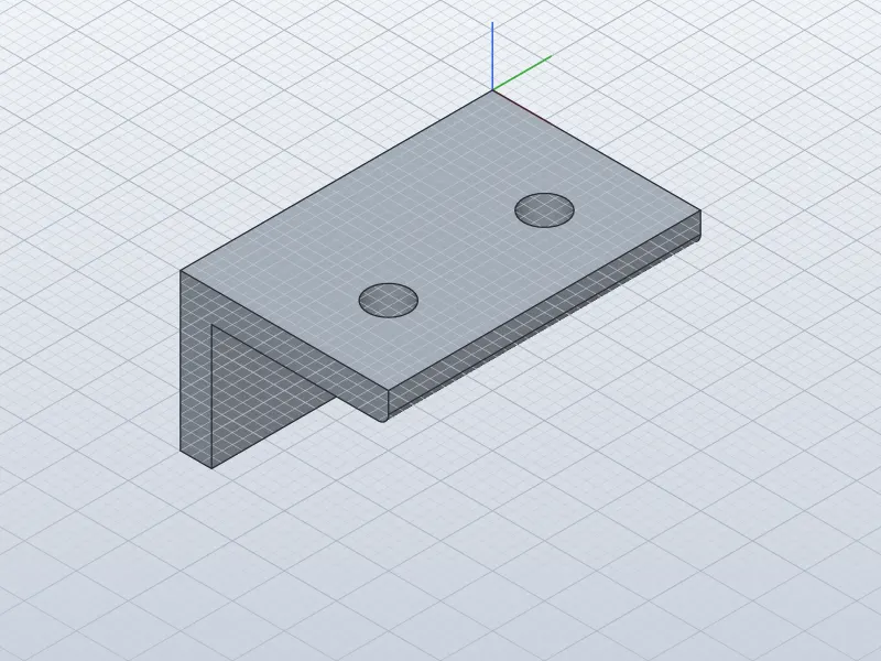
The repo ships an example script, examples/bracket.json. A script is a JSON list of the same commands the UI runs. This one defines two parameters, draws an L-shaped profile on the XZ plane, extrudes it, rounds one edge, cuts two holes, and is a complete parametric part in 12 commands:
{"commands": [
  {"command": "parameters.change", "params": {"name": "width", "expression": "60 mm"}},
  {"command": "parameters.change", "params": {"name": "thickness", "expression": "6 mm"}},
  {"command": "sketch.create", "params": {"plane": "XZ", "name": "Profile"}},
  {"command": "sketch.line", "params": {"points": [[0, 0], [40, 0], [40, 6], [6, 6], [6, 30], [0, 30]], "closed": true, "ids": ["a", "b", "c", "d", "e", "f"]}},
  {"command": "sketch.finish", "params": {}},
  {"command": "solid.extrude", "params": {"distance": "width", "direction": "negative", "body_name": "Bracket"}},
  {"command": "solid.fillet", "params": {"edges": [[40, -30, -6]], "radius": 2}},
  {"command": "sketch.create", "params": {"plane": "XY", "name": "Holes"}},
  {"command": "sketch.circle.center", "params": {"center": [25, -15], "diameter": 8}},
  {"command": "sketch.circle.center", "params": {"center": [25, -45], "diameter": 8}},
  {"command": "sketch.finish", "params": {}},
  {"command": "solid.extrude", "params": {"distance": "thickness", "direction": "negative", "operation": "cut"}}
]}
Read it as a recipe. The profile is an L: 40 mm wide, 30 mm tall, with a 6 mm leg. It is extruded by the width parameter (60 mm), one edge is filleted at radius 2 mm, and two 8 mm holes are cut through the 6 mm leg. Save it as bracket.json and run it:
solidcraft-cli run bracket.json --out bracket.step --save bracket.sc --results --timingsThe run finished in 1,014.6 ms total — about a second — and produced bracket.step (22,369 bytes) and bracket.sc (15,587 bytes, the saved design). Nothing failed, and no timeline feature was rolled back. Now measure what you built. eval opens a design and reports exact mass properties from the SMLib kernel:
solidcraft-cli eval --in bracket.sc --json-out eval.jsonThe measurement says: one body, "Bracket", a closed solid with a volume of 22,385.31 mm³, a surface area of 9,215.31 mm², a mass of 28.88 g, and a bounding box of 40 × 60 × 30 mm. It has 11 faces, 27 edges, and 18 vertices. The timeline lists five features — Profile sketch, Extrude1, Fillet1, Holes sketch, and the cut extrude — each with its own build time; the fillet was the slowest at 29.6 ms. The STEP file contains one MANIFOLD_SOLID_BREP, which is the check that the export is a real solid and not a surface shell. If any of these numbers differ on your machine, something in the run differs; the numbers above are what a correct run produces.
Step 3 — Change a parameter and watch it rebuild
A parametric model earns its name here. The extrude distance is not 60 mm written into a feature; it is the parameter width. Change the parameters and re-run the timeline on top of the saved design:
{"commands": [
  {"command": "parameters.change", "params": {"name": "width", "expression": "80 mm"}},
  {"command": "parameters.change", "params": {"name": "thickness", "expression": "8 mm"}}
]}
solidcraft-cli run param-change.json --in bracket.sc \
--out bracket-80.step --out bracket-80.stl --save bracket-80.sc
solidcraft-cli eval --in bracket-80.sc --json-out eval80.jsonTwo details in that command are worth keeping. First, --in opens the saved design and the script runs on top of it — a script without --in starts from an empty design, and --in alone only opens and exports. Second, --out is repeatable: one run emitted the STEP file and the STL file together. The rebuilt part measures:
| width 60 mm, thickness 6 mm | width 80 mm, thickness 8 mm | |
|---|---|---|
| Volume | 22,385.31 mm³ | 30,048.14 mm³ |
| Mass | 28.88 g | 38.76 g |
| Bounding box | 40 × 60 × 30 mm | 40 × 80 × 30 mm |
| Faces / edges | 11 / 27 | 11 / 27 |
The volume grew by about a third, the bounding box stretched exactly 20 mm in the extrude direction, and the topology — 11 faces, 27 edges — did not change, which is what a clean parametric rebuild looks like: the same features, new dimensions. The STL export (57,784 bytes) is ready to slice for a 3D printer, and the STEP file (22,761 bytes) opens in any other CAD tool. This is the property that makes the next step possible: an agent that can change a parameter can redesign the part, not just redraw it.
Step 4 — Hand the model to an AI agent over MCP
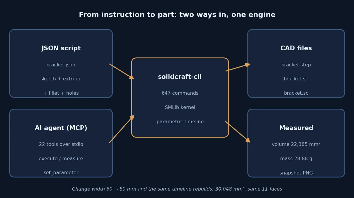
solidcraft-cli mcp is a Model Context Protocol server over stdio (JSON-RPC 2.0, one message per line; protocol revision 2025-06-18). An agent models exactly like a person does: every tool runs engine commands — the same ones the toolbar, palette, and scripts use — and never opens a dialog. The server in 0.42.0 exposes 22 tools: list_commands, describe_command, execute, batch, inspect_design, measure, body_topology, set_parameter, check_parameters, screenshot, compare_picture, export, crash_reports, running, pending, cancel, undo, redo, new_design, open, save, and skill_reference.
I verified the server directly, without any agent or API key, by speaking the protocol to it from a small Python client. The handshake:
→ {"jsonrpc": "2.0", "id": 1, "method": "initialize",
   "params": {"protocolVersion": "2025-06-18", "capabilities": {},
              "clientInfo": {"name": "verify", "version": "0.1"}}}
← {"id": 1, "jsonrpc": "2.0",
   "result": {"serverInfo": {"name": "solidcraft", "title": "SolidCraft",
              "version": "0.42.0"}, "protocolVersion": "2025-06-18", ...}}
Then the tool list (22 tools, as above), and the agent-style write — build a box through execute, then inspect and measure it:
→ {"jsonrpc": "2.0", "id": 3, "method": "tools/call",
   "params": {"name": "execute", "arguments": {
     "command": "solid.box",
     "params": {"length": 20, "width": 10, "height": 5, "body_name": "MCPBox"}}}}
← {"content": [{"text": "{... \"created_bodies\": [\"MCPBox\"], \"feature\": 1,
   \"ms\": 20.9269, \"name\": \"Box1\", ...}"}], ...}

→ {"jsonrpc": "2.0", "id": 4, "method": "tools/call",
   "params": {"name": "measure", "arguments": {}}}
← {"content": [{"text": "{... \"area_mm2\": 700.0,
   \"bbox\": {\"max\": [20.0, 10.0, 5.0], \"min\": [0.0, 0.0, 0.0]}, ...}"}], ...}
The box landed in 20.9 ms, inspect_design confirmed the body MCPBox in the design, and the measurement is exactly right for a 20 × 10 × 5 mm box: a surface area of 700 mm², which is 2 × (200 + 100 + 50). That is the whole agent loop in miniature — list the tools, execute a command, inspect the design, measure the result — and it works with no account and no key, because the protocol itself needs neither.
To use it with a real agent, the README's registration for Claude Code is:
claude mcp add solidcraft -- solidcraft-cli mcpThat command is documented in the README; I did not run it here, because Claude Code needs an Anthropic account and this sandbox has none. Once registered, the agent gets the same 22 tools, and you can ask it to model a part, change a parameter, and export the STEP file — then check the measurement yourself with eval, exactly as in Steps 2 and 3. Two safety properties are worth knowing. First, file access is scoped: tool calls can only reach the folder of the open design, the server's own scratch folder, and folders you name with --allow-path — the working folder alone does not count, and hidden folders are out of reach by default. Start the server with solidcraft-cli mcp --allow-path ~/designs for the folders your agent must reach. Second, the server can also drive the running desktop app instead of a headless session (solidcraft-cli mcp --connect 127.0.0.1:7878 after starting the app with solidcraft --control 7878), so you can watch the agent model — that bridged mode needs a display and was not run here.
Step 5 — Render the part without a GPU
The snapshot in this article's second image is not a screenshot of a GUI. It is the CLI's own render of the bracket design, made on a machine with no graphics card:
solidcraft-cli snapshot --in bracket.sc --out bracket.png --width 800 --height 600
# {"bytes": 607062, "height": 600, "path": "bracket.png", "renderer": "cpu",
#  "warning": "drawn by the CPU rasterizer (no GPU adapter qualified, or
#  SOLIDCRAFT_GPU=cpu): surface analysis colours, highlights and legends are
#  not drawn; ...", "width": 800}
The command exits 0 and writes an 800 × 600 PNG (607,062 bytes). The warning is expected, not an error: with no GPU adapter, the CPU rasterizer draws the model and skips surface-analysis colours, highlights, and legends. The render shows the L-bracket, both holes, and the grid — enough to check a part at a glance in a scripted pipeline, and the same screenshot tool exists over MCP, so an agent can look at what it just built. A full path-traced render subcommand also exists, with progressive sampling and exposure controls; the snapshot is the fast check, the render is the pretty one.
When to use this vs alternatives
SolidCraft is the right tool when the deliverable is a parametric solid and the workflow is scripted or agent-driven. A JSON script that builds a bracket is version-controllable, diffable, and re-runnable; an MCP agent that can call set_parameter and measure can iterate a design against a target volume instead of guessing. FreeCAD is the mature open-source alternative — larger feature set, Python scripting, a decade of parts libraries — but it has no MCP server, and its scripting is a separate API from its GUI rather than the same command registry. Onshape and Fusion 360 are the polished commercial options with cloud collaboration and CAM, at subscription prices and with your designs on someone else's servers. OpenSCAD is the classic script-first modeller, but it is constructive solid geometry without a constraint solver: no sketches, no dimensions that drive a solver, no fillet on a named edge. And the LLM-mesh route — generating STL triangles from a prompt, as in our Sand3D tutorial — gives you a shape, not a parametric solid you can edit, measure, and export as STEP.
Do not use SolidCraft yet for production engineering. The README's own scope is "simple parts", the oracle count is 75 of 76, and the release pace — 80 releases in five weeks — tells you the ground is still moving: a design saved in 0.42.0 uses a newer file format than 0.30.x, and the plugin runtime is explicitly experimental. For a bracket, an enclosure, a jig, or a prototype you can hold in your hand, it is already usable; for a part someone's safety depends on, use a mature tool and check the result in it — which you can do, because the STEP export is standard.
The takeaway
SolidCraft is a parametric CAD kernel with an agent-shaped front door. In about a minute of terminal work you can install 0.42.0, run the repo's bracket script, measure a closed solid to the cubic millimetre, change two parameters and watch the same timeline rebuild with new dimensions, and drive the same engine over MCP with 22 tools — all without an account, a key, or a GPU. The project is five weeks old and moving fast, so treat it as a sharp tool for simple parts rather than a finished workshop. But the direction is the story: CAD where the script, the agent, and the person all run the same commands, and the measurement at the end is the same either way. Start with the bracket, change the numbers, and check the volume — that loop is the whole product.
Sources
- tangency-labs/solidcraft on GitHub — repository, README, stars, and install instructions
- SolidCraft v0.42.0 release — release notes, asset list, and SHA256SUMS
- SolidCraft and AI agents (MCP) — server protocol, tool list, file scoping, and Claude Code registration
- Scripts — JSON command format and the bracket-style examples
- examples/bracket.json — the bracket script run in this guide
- Open Source AI Radar, Week 45 — SolidCraft at about 15,800 stars on November 12, 2026